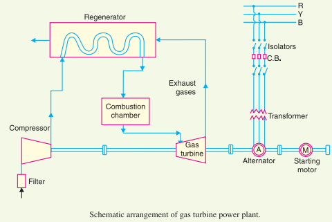
Gas Turbine Schematic Diagram
Gas turbine engine schematic Turbine gas diagram schematic engine fig Gas turbine power plant schematic diagram
Closed Cycle Gas Turbine: Construction, Working, diagram - Mechanical
Cogeneration power-desalting plants using gas turbine combined cycle [diagram] gas turbine jet engine schematic diagram Turbine diagram
Turbine diagram schematic
Gas turbines – ryno drillingSchematic diagram of gas turbine power plant Closed cycle gas turbine: construction, working, diagramTurbine electrical4u.
[diagram] gas turbine propulsion systems diagramSpecific power turbine gas engine diagram turbines energy education powers aircraft because figure very they large Gas-turbine engine| gas turbine engine schematic diagram of the experimental unit.

Schematic diagram of gas turbine
Turbine gas diagram cycle closed working pv various mechanical booster construction processes usedGas turbine diagram Turbine gas working types components principle burner engineeringEngine jet turbine gas sketch station schematic nasa numbers aircraft engines parts number gif airplane modern location each military drawings.
Gas turbine power plant schematic diagramAll you should know about combined cycle gas turbine Turbine brayton schematic jouleGas turbine turbines generation 7mw electricity.

Gas turbine plant power diagram schematic layout station
Turbine engine salient depictingGas turbine schematic diagram. How is material science and technology helping people?Turbine plant combined.
Turbine sectional diagramSchematic diagram of a simple gas turbine power plant Gas turbine components and principle [complete explained]Gas turbine power plant.

Gas turbine diagram flow simple turbines electric cycle axial starting general support pg unit tutorials
Schematic diagram of gas turbine power plantInside a ge lm6000 (cf6-80c2) gas turbine Turbine gas cycle power combined cogeneration using desalting plantsSchematic diagram of a steam and gas turbine [5]..
Turbine gas cycle plant power combined schematic system stock shutterstock vector generator engine steam compressor air find plants marine stuffSpecific power The schematic diagram for a simple gas turbine.Cross-sectional view of the gas turbine generator.

[diagram] ge lm2500 gas turbine diagram
Gas turbine schematic diagramTurbine lm6000 gas ge cf6 80c2 compressor lpc compression Schematic diagram of a gas turbine engine.Gas turbine schematic diagram.
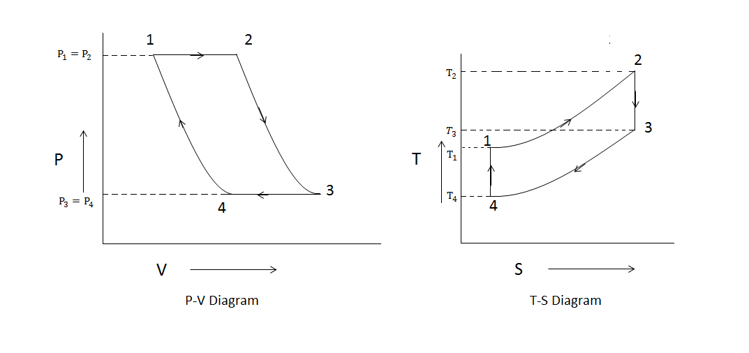
Gas turbine cycle(brayton cycle/joule cycle)Gas turbine schematic and station numbers Gas turbine diagramAll about general electric pg 9171 e gas turbine.

Turbine gas engine energy combustion cycle engines pressure internal open used conversion britannica compressor wallpapers exhaust high turn velocity constant
8 flow diagram of a simple gas turbine-steam turbine combined powerGas turbine combined cycle power plant system schematic stock vector .
.
Closed Cycle Gas Turbine: Construction, Working, diagram - Mechanical

Gas Turbine Diagram

8 Flow diagram of a simple gas turbine-steam turbine combined power

| Gas turbine engine schematic diagram of the experimental unit

Gas Turbine Schematic Diagram
![[DIAGRAM] Gas Turbine Propulsion Systems Diagram - MYDIAGRAM.ONLINE](https://i2.wp.com/www.researchgate.net/profile/Ahmed_Hafaifa/publication/311788922/figure/download/fig5/AS:441725874380806@1482327063653/Schematic-block-diagram-of-Gas-turbine-system.png)
[DIAGRAM] Gas Turbine Propulsion Systems Diagram - MYDIAGRAM.ONLINE